
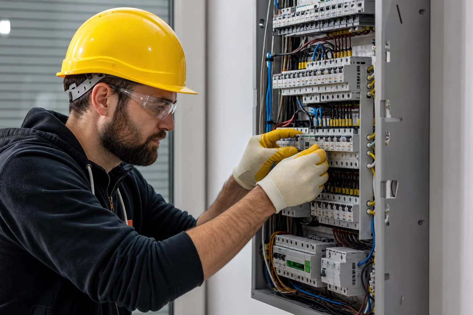
Proper installation ensures operational reliability, prevents fire hazards, and protects sensitive equipment from unexpected power surges and thermal overloads.
Location Selection and Thermal Management
Mount the voltage stabilizer in a dry, well-ventilated utility area away from direct sunlight, flammable substances, and moisture sources. Regulators generate heat during continuous step-down or boost transformations, requiring at least twenty centimeters of clear space around the cooling grilles. Poor airflow causes internal thermal cutoffs to trip prematurely, degrading capacitor banks and transformer coils over time.
Maintain minimum 200 mm clearance on all sides to allow natural convective airflow through heatsinks.
Select pure copper wiring rated for maximum surge currents; torque terminal screws to specification.
Electrical Connection & Earthing Protocols
Connect input and output lines through dedicated circuit breakers with appropriate tripping curves. Dedicated grounding is mandatory; floating neutrals or ungrounded chassis introduce dangerous ground loop voltages and compromise internal surge protection components like metal oxide varistors.
- Install an upstream dual-pole or triple-pole circuit breaker matching the stabilizer rated input amperage.
- Verify solid ground bonding with low resistance path (< 4 Ohms) to ensure surge suppression works effectively.
- Double-check phase rotation and terminal block screw torque after 48 hours of initial load operation.